A Journey in Watchmaking by David Cottrill

A Journey in Watchmaking by David Cottrill

  • Post category:General

Starting from Scratch, Part 1

Looking back it is hard to remember that eight years ago the idea of making my own pocket watch from scratch was something bordering on the impossible. Back then an article on the BBC website had caught my eye that was to be the start of a life-changing journey; not that I knew that then. There was something in the title along the lines of ‘the world’s greatest horologist’, the article revealed the outline of a man then new to me, George Daniels. That one man could make all the parts of a watch from raw materials was a revelation and also seemed to be suggesting something of a personal challenge.


Figure 1. Watch No 1

With the first pocket watch completed, Figure 1 & 2, and a second, to my own design well under way, this article describes the journey to date. Starting from scratch with limited equipment meant designing and making whatever was needed to get the job done, not to mention the inevitable set-backs as well as triumphs along the way. 

While having no background in horology I was once a toolmaker at a Borg-Warner factory that made automatic gearboxes. As well as making production tools and gauges to high tolerances inevitably some time was also spent investigating quality issues with the production of gears. This experience, coupled with the realisation that it might be possible to create a small mechanism that was functional, useful and attractive was the spur to making a start. So armed with a copy of ‘Watchmaking’ by Daniels work commenced on the first pocket watch.

A conscious decision was made to focus on making a functioning movement to the design by Daniels, nothing more and nothing less. A perfect black polish could wait for watch number two, there being no point in finishing a part to a high standard when it may not perform as expected, if at all! I firmly believe that this focused direction was the most important factor in being able to complete the first watch.

Figure 2. Watch No 1 movement in temporary protective oak ‘box’ waiting case and dial

The first major task was to devise a method of cutting wheels and pinions. While designing and making a dividing attachment for the headstock of the Unimat was fairly straightforward the standard milling capabilities of the machine were not particularly satisfactory. The barrels were cut purely on the lathe with the Unimat milling attachment on the cross slide, though in all honesty this was not rigid enough and needed very careful use.

Figure 4. The finished fourth wheel.

In ‘Watchmaking’ Daniels refers to the ‘Cork and Nail’ method as a way of describing the manufacture of a watch by hand with very basic equipment. Encouragingly he also points out that while sophisticated machinery is a great help, it is not essential to the making of the various parts of a watch. So an old Unimat 3 lathe was retrieved from the garage and refurbished as best as possible.

Figure 3. Machining the fixed Fourth Wheel.

With hind-sight, and having long since upgraded equipment (which now includes Pultra and Schaublin lathes) such an approach looks impractical. However it did work, so there is a lesson here, make the best use of what you have and don’t let the lack of what might seem essential equipment deter you from getting started. With a bit of careful thought and a large helping of patience there is usually a way forward.

In an effort to improve matters all the other wheels and pinions were cut by clamping the Unimat to the table of a larger bench mill, which was found to be far more satisfactory. The lathe then acts as a self-contained dividing head with integral tail stock, Figure 3 & 4.

With the barrels made there was no escaping the need to make the first set of very small screws to secure the star wheel of the Geneva stop work. This was the first of many requirements that were outside the experience of a tool room apprenticeship and as a result often required several attempts and more than one re-think. Making screws is now a routine job as the style of head, slot and finishing have been decided upon, with the necessary tooling to hand; but thinking back the production of that first pair of usable  0.5mm screws was something of a personal achievement. Indeed, the whole process of making the first watch showed that it is best to treat each new challenge as a learning exercise and not to expect the first part to be perfect.  This was a big change as when working at ‘normal’ sizes it was considered a bad day in the toolroom if a second part needed to be made, yet alone several to get things right!

As well as treating each challenge as a learning exercise it also helps to think about the repeatability of any process, from simple tool sharpening to the machining of a complex part. It is always easier to do the right thing if the facilities are readily to hand. For example, having a second bench for all tool sharpening and heat treatment work has saved time as well as reducing the chance of cross-contamination. The actual facilities do not need to be grand, but taking the time to ensure that everything required is conveniently laid out makes all the difference. Watchmaking needs all the patience and concentration that you can muster; you don’t want to waste any of that precious resource hunting for things.

Another valuable lesson is that time spent making tools and jigs really is well spent, as is putting some thought into how best to record methods and processes that worked well. It is always tempting to push ahead with some basic (dare I say crude) lash-ups to keep things moving to make the next part. The making of good tools and equipment is an investment for the future and the next job will get done a lot quicker and the results will be assured. In addition, as the complete design for the second watch is in CAD as a 3D model this also contains detailed process notes for the parts. Rather than recording the details in a separate note book the instructions are part of the drawings, making them easy to find and copy when designing the next watch.

The making of the lever for the escapement in the first watch is a good example of a detour into equipment design that resulted in a machine that is very versatile and now indispensible. I had chosen to make the watch with a Daniels Co-axial escapement and making the lever to the required tolerances was proving difficult without access to an accurate jig borer. It looked as though this component had the potential to bring work on the first watch to a halt if a solution could not be found.

Figure 5. BCA Jig, borer and custom made centering microscope.

‘Watchmaking’ details the geometry of the Co-Axial escapement and tells you how to draw out the mechanism to a large scale from which dimensions can be taken. A method of marking out the lever is then suggested which looks reasonable enough on the page, however it became clear within five minutes that my ability to mark out accurately and then drill the required holes in a rather small piece of steel was just not going to happen.

A different approach was needed that played to my own strengths to prevent the manufacture of this part becoming a show stopper. In an ideal world a small Swiss jig borer would have been acquired from day one, however this was not justifiable at the time (back then this was a weekend and spare time endeavour) so best use had to be made of the nearest equipment to hand. This was a small mini-drill complete with a not very accurate compound table, but it was sensitive enough to drill small holes. A couple of brackets were machined up so that dial gauges could be fitted to the compound table. These would be used to correctly position the slides for the key drillings and this served for the first few attempts at making the lever. The watch even ticked with one of these early versions, though very unreliably and more by luck than judgement. Encouraged by this progress a better solution was sought.

The better solution entailed spending a number of months worth of ‘spare time’ refurbishing a BCA jig borer and designing a new spindle based around precision angular contact bearings, Figure 5. Fittings were also made to attach Mahr digital dial gauges to the X and Y axis. The BCA with its improved spindle (taking standard ‘ER’ Collets) a sensitive drilling quill and microscope made the manufacture of the lever far more certain and quicker.

Figure 6. Accessories drawer for the BCA.
Figure 7. Hour hand at early stage of making.

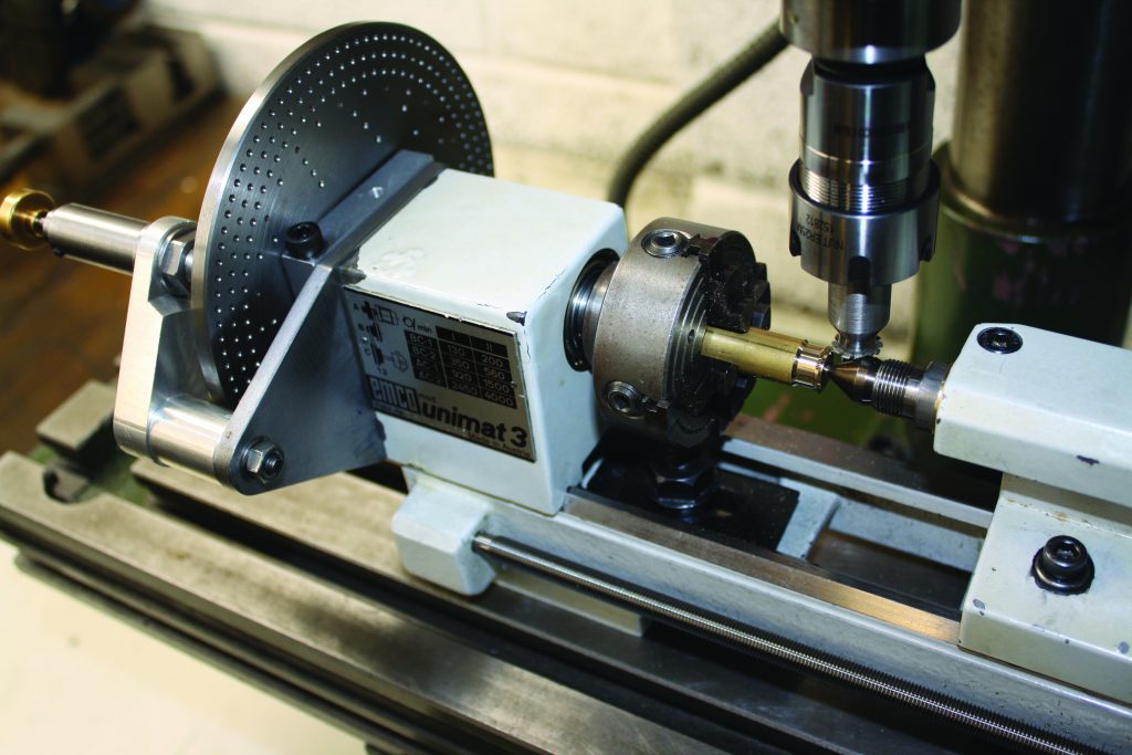
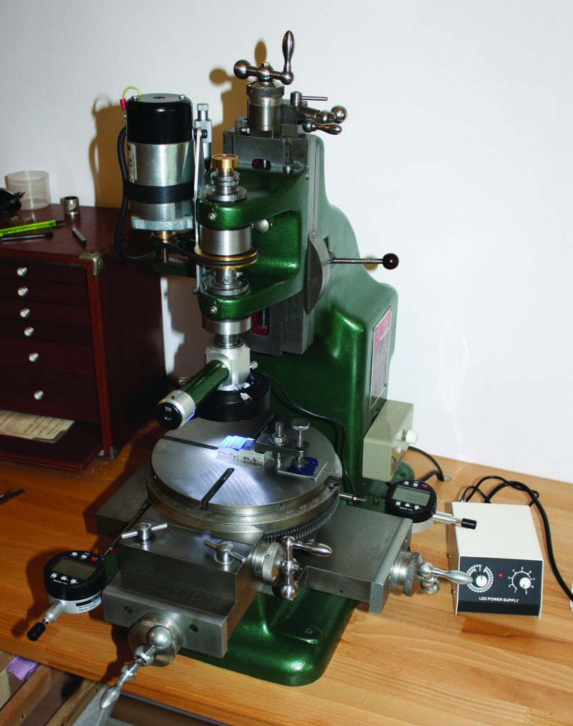
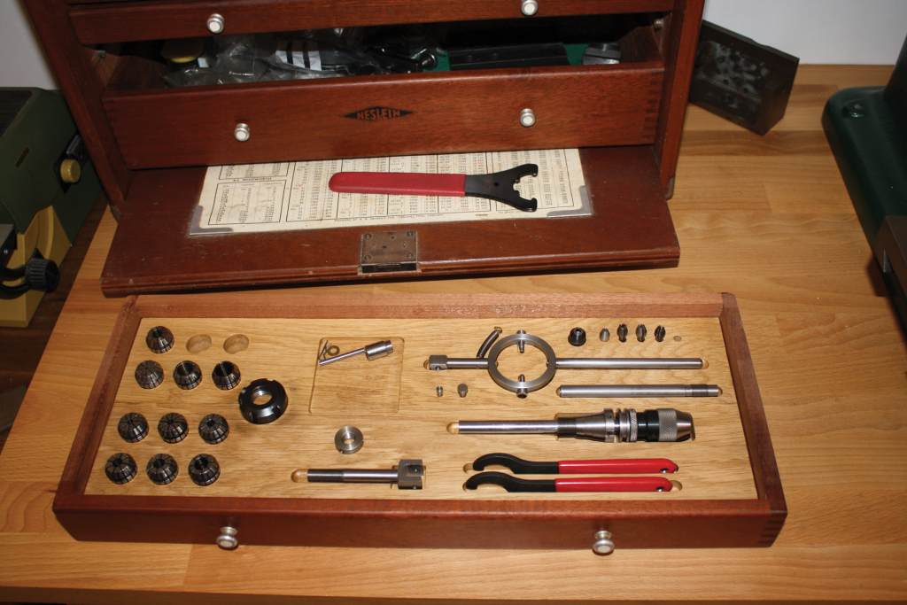
Over time accessories have been made to integrate the BCA with other equipment as it was acquired, for example Pultra 10mm collets and chucks can be used in the centre of the rotary table. Work can now be transferred between the Pultra lathe and the BCA, speeding up work and simplifying the machining of complex bridges and plates, Figure 6.

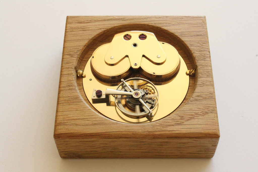
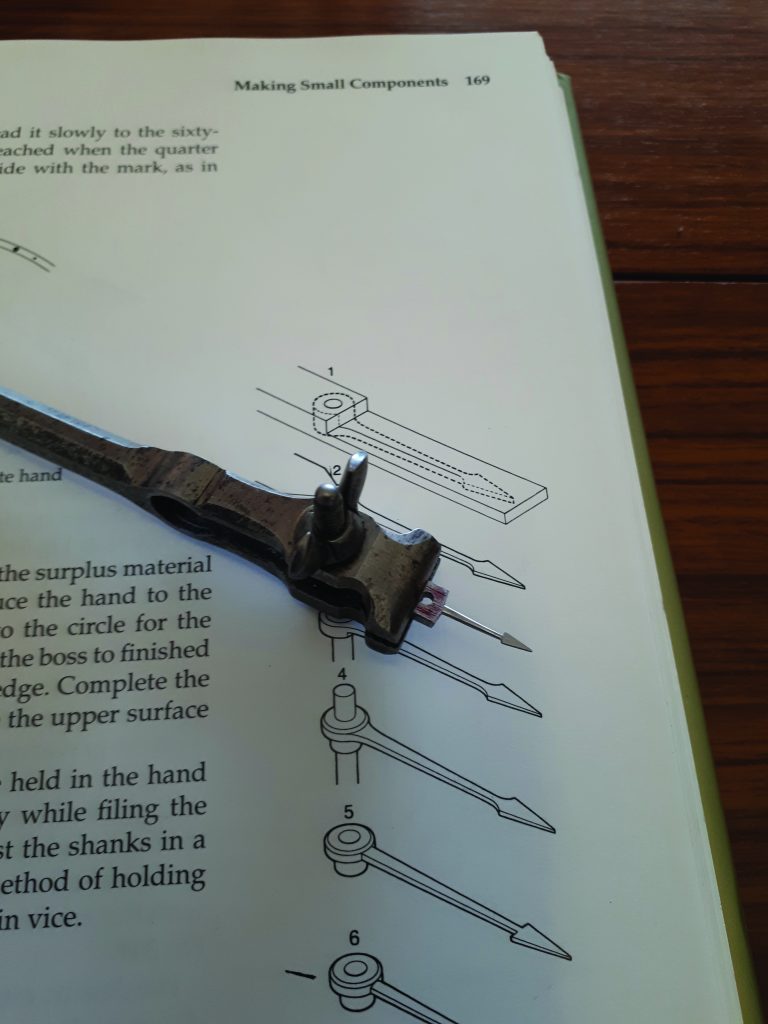
The lever went through a number of iterations before errors in interpretation of geometry as well as making were ironed out. Eventually version 12 was fitted to the movement and finally it ticked in a much more satisfactory manner and continues to do so today.

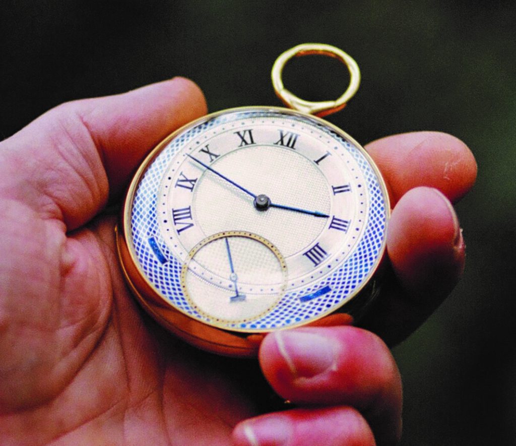
At this point you may be thinking what about case making and related components (Figures 7, 8 & 9), jewelling, burnishing pivots, forming a terminal curve and a myriad of other techniques? Yes they have all required their fair share of effort and as with many other aspects have been continually refined over time. For example all the pivots for the first watch, including the balance staff, were machined in the lathe as if they were of a more normal size, not a graver in sight! Since then a Boley F1 has been acquired together with a draw full of various gravers.

Readers may also be interested to know that while this project was driven mainly by the writings of George Daniels, a second George, has been an invaluable mentor. Some may have equipment that they have either purchased or made themselves based on the designs of Geo H Thomas1. There is much to be learned from his books on the approach to designing tooling and general problem solving at the small scale.

Figure 8. Tipsy key ready for final finishing and guilding
Figure 9. Checking the fit of the movement in the part finished case

Part 2 of this article will cover the making of the engine-turned dial together with an update on the progress of the second watch. Additional pictures are also posted on Instagram @djcottrellwatches

References

1. The Model Engineers Workshop Manual

Tee Publishing ISBN 1-85761-000-8