
Part 1 – Making the Annulus Wheel
I have recently graduated from Birmingham City University with a first class honours degree in Horology. I came to the course with no prior experience, but a keen interest in all things mechanical. It was an exhibition featuring George Daniels at the Science Museum, and then Roger Smith’s videos on YouTube, that brought horology to my attention as a 17 year old; and since making the decision to pursue this career, I’ve worked hard to achieve as much as possible within the limited time a three year degree course offers.
For my final year project, I needed to produce a working horological mechanism. I wanted to make something that would showcase my abilities, whilst at the same time being achievable in the given time-frame. Whilst researching different clock types, I stumbled across an epicyclic clock in Derek Roberts’ British Skeleton Clocks, 1987, and from the first moment I saw the photos, I knew this was the perfect clock for me to make.
This article, which will be published in two parts, will describe the trials and tribulations of making two particular parts of my clock: the Annulus wheel and the Spider Arm, which are the defining components of the mechanism. But first, a look at the history of the clock and my design.
What is an epicyclic clock?
An epicyclic clock uses epicyclic gearing, commonly known as planetary gearing, for its going train. I won’t go into detail on what planetary gearing is, but a quick search on Google will provide all the information you need. Early examples of epicyclic gearing in horology can be seen in the Antikythera mechanism and De Dondi’s Astrarium, where they used the gearing to show the position of Venus and the motion of the Earth’s moon, respectively.
The original epicyclic clock was designed by William Strutt in the 1820s. Strutt was a mechanically minded man with numerous inventions attributed to him, and although his horological life isn’t as well documented as his engineering achievements, he was the first person to apply epicyclic gearing to the going train of a clock. He died in 1830. A memoir in the Derby Mercury shows that Strutt was highly regarded in the community, saying, ‘It would be no easy task to give a full account of the public works in which he took a part, as it would be little less, than to describe the various improvements which have taken place in the town of Derby, for the last fifty years.’ (Unknown, 1831, P3.)His design was produced by his friend, William Wigston, and it is presumed the first clocks were made in 1831, one being signed ‘W. Wigston. Derby. W. Strutt, Esq. Invt.’. Very few have ever been produced due to the complexities involved in the manufacture. Between 1973 and 1974, E Dent & Co. Ltd produced a total of 100 epicyclic clocks, which were mainly sold into the USA for $3,500.
My design
Now knowing what type of clock I wanted to produce, it was time to put my own creative stamp on it. From the outset I knew that I wanted to create a unique piece, however, before changing anything, I needed to understand more about the clock, otherwise I might inadvertently change something that shouldn’t be changed. The only source I could find was William R Smith’s book, How To Make A Strutt Epicyclic Train Clock, 2003, which gives a detailed set of instructions on how to make Strutt’s clock from start to finish. The book was instrumental in this project and without it, I would have been lost on the nuances of this type of clock.
The first major changes to my design, were to the escapement and power delivery. In the third year of the degree, time is the enemy. There are simply never enough hours in the day, so I had to be realistic with my design as I only had around four months to produce the clock.
The original escapement was a deadbeat, but I decided to change it to a recoil, choosing Gazely’s design from Clock and Watch Escapements, 1956. This was because his recoil and deadbeat designs share the same centre distances, so in theory, I could swap to a deadbeat later in the production if time permitted.
Next, power delivery. I decided to take out the fusée from the design and keep it simple with just a barrel, although I did add intermediate winding to the setup. This was done after a visit from Roger Smith, who graciously looked over my design, and declared my winding situation to be ‘unacceptable’, due to only being able to wind the clock when the planetary gearing wasn’t obstructing the square! Not one to argue with a world-class watchmaker and designer, of course I added intermediate winding.
Next was the train count. I did this for a purely aesthetic reason as I wanted the components to compliment my design of the clock rather than feel like two separate entities. An example of this is when looking at the dial, face on; I wanted to be able to see the internal teeth, but without a free train count, I would be forced to change the dial and the overall look to something that I didn’t want.
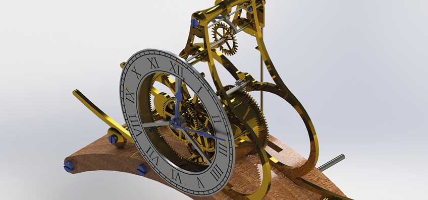
My final decision was to wall mount the clock. This further allowed the train count to be free, as the length of the pendulum wouldn’t be a concern. And, as I intended to keep the clock, it would
definitely need to be wall mounted, as there wasn’t an appropriate space for it at home, Figure 1.
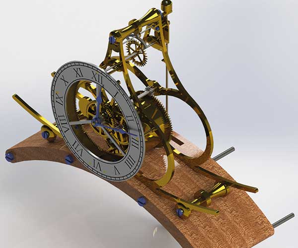
Figure 1. My final design.
Annulus wheel and Spider arm
First, here is a brief overview of these components:
The annulus wheel has internal teeth which interact with the planet wheel and external teeth for engaging with the escape pinion.
The spider arm is its accompanying component which will hold the annulus wheel and has spacers to offset it. This is done to allow the planet wheel and its arm to revolve around the internal teeth as seen in Figure 2.
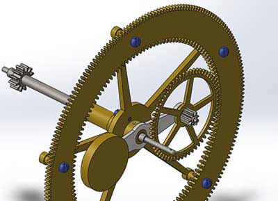
Figure 2. CAD render of the action of the Annulus wheel and Spider Arm.
Both parts are made together. This is done to ensure perfect concentricity, as without it, the annulus wheel will run elliptically rather than in a circular motion. This would cause major depthing errors and as the annulus wheel and planet wheel are tooth-to-tooth, the scope for error is minimal.Perhaps as you are reading this, more challenges with my design are now becoming apparent, and all are centred around concentricity. Without going into too much detail, if any component in Figure 2, is not concentric, then the clock will bind and not run. This also meant that I had to work to much tighter tolerances, typically aiming for somewhere between perfect and 0.02mm otherwise the part would need to be remade. This was made possible by having access to Schaublin 70 lathes at university.
The Cutting Frame
The cutting frame is designed to gain access for cutting the internal teeth. Smith provides engineering drawings of the cutting frame in his book. The logical first step was to create a 3D model of these drawings and then check to see if it would clear my annulus wheel. This was one of those moments where the time spent designing the clock in CAD really paid off. It was immediately obvious that the frame was too big, so I quickly redesigned it and its accompanying parts, to work with the dimensions of my wheel, see Figure 3.
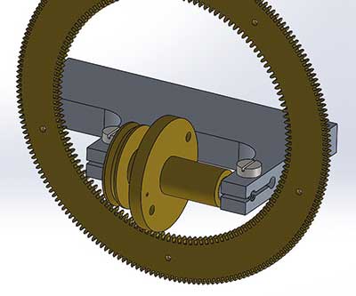
Figure 3. CAD render of the cutting frame and annulus wheel in situ.
The cutting frame is held in an engineer’s vice, which in turn is fitted to a vertical slide. The frame needs to have the arms protruding so the Thornton cutter doesn’t hit it and can pass through the annulus wheel, to cut the full tooth depth. The cutter is attached to the brass rotor and acts like a fly cutter when it’s locked in place with a small pin. The rotor has ball bearings pressed in the sides and runs on two spigots that are threaded into the frame; power is provided by a secondary motor.
The Wheel Mandrels
Two mandrels must be made for the annulus wheel: one for internal teeth and one for external teeth. The internal teeth mandrel is bowl shaped, as it needs to be bored out so that the cutter has clearance when cutting the internal teeth. The external teeth’s mandrel has a sacrificial aluminium plate attached to it which the internal teeth fit on to, (more will be explained in Part Two of the article.)
The mandrels needed to be: made of a strong material, able to be bolted to the faceplate and be able to be taken off and relocated if necessary. I consulted the University staff who suggested tufnol or nylon, as we had these materials in stock. I decided to use nylon because we had a cylinder of ø14” which I thought I could turn easily. Oh, how wrong I was!
Having cut the cylinder into the sections I needed for the mandrels, I tried to fit it into our biggest lathe, a Colchester Student, but it wouldn’t fit! This was due to additional safety features which had been retro-fitted to the lathe. The solution was to slice up the piece so it would fit in a four jaw chuck. As can be seen in Figure 4, the final shape was irregular and time-consuming to machine, taking me a full ten-hour day to turn the pair – but it was well worth investing the time.
The mandrels needed to be secured and located to the faceplate. After much deliberation, I decided that the best way to do this would be to fix locating pins and M10 bolts to the mandrels. I started by drilling the centre of the mandrels so that a locating piece could align the mandrel, indexing plate and faceplate together. By making it a tight fit, I ensured the location was perfect. From here, eight 2mm holes were drilled and steel rods driven in for locating, then I drilled and tapped four M10 holes which would hold the pieces together. One of the great things about nylon, is that when the bolts are tightened up, it acts like a nyloc nut and won’t come apart easily. Finally, the mandrels were assembled and fitted onto the Myford and turned true to the final dimension.
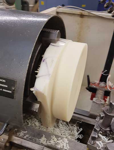
Figure 4. Turning the irregular shaped mandrel.
Indexing the Wheel
Indexing the wheel is one of the most important parts of the setup because, if not well made and secure, it may move while it is being cut, or there could be a partially formed tooth at the end of cutting. We discussed many ideas as to the best way to index the wheel. Smith used a Sherline rotary CNC indexer which fixes to the back of the spindle by a modification to the Myford division plate. This idea sounded the best and there was even a rarely used indexer in the workshop, however we didn’t have the divison plate and the cost for a new one wasn’t viable.
Other ideas, such as indexing it through the gearing for thread cutting on the back of the Myfordand attaching an expanding mandrel to the back of the spindle with a homemade division plate, were thought about but ultimately not used due to the amount of time it would take.
In the end, the solution I chose was a manual indexing setup with a homemade division plate. As the wheel needed a mandrel which would be fitted to the faceplate, I decided that the division plate would be best sandwiched between the faceplate and the mandrel. The locking detent setup would then be clamped to the floor of the Myford and could be operated manually.
I made the plate from 5mm acrylic which was lasercut at the BCU School of Jewellery campus. Acrylic was chosen because it could easily be lasercut on site, whereas a metal plate would have had to be setup and drilled, or taken to the main university campus where there is a waterjet cutter and larger laser cutters – both taking much longer than lasercutting acrylic.
Choosing the indexing hole sizes was an important step as acrylic is quite brittle. I didn’t want to make the gap between holes too small, which might cause it to crack, but I also wanted to have the largest holes possible so it was as rigid as could be. After a few tests, I decided on ø3mm for the internal teeth and ø2mm for the external teeth.
The last feature added were the faceplate slots. I wanted to avoid drilling holes in the acrylic if possible, so I added the slots which were laser cut at the same time as the indexing holes. This idea worked out perfectly and was very helpful. Figure 5.
To index the plate, it was suggested I use a silver steel rod which would spring in and out of the holes; I created a holder from steel and wood, Figure 6, and clamped it to the lathe floor. The rods were turned to the index hole diameter with a 90° bend on the end.
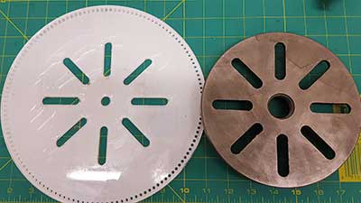
Figure 5. The external teeth indexing plate.
Figure 6. The first indexing setup.
Mounting the Vice and Motor
As I mentioned earlier, the cutting frame is held in a vice on a vertical slide. I had to make my own T-nuts for fitting the two together and my own custom adaptor jackets so that the M6 bolts would fit snugly in the M8 holes in the vice, Figure 7. A rather strange design decision, in my opinion, by Myford as the T-nuts are not designed for bigger than M6, but it was well worth it as the setup was as solid as a rock.
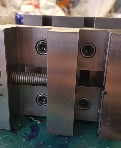
Figure 7. External teeth indexing plate.
Next, was how to mount the secondary motor to the cross slide. I decided to use two 3mm thick steel plates that would allow the motor to be attached and could then be bolted to the cross slide. The motor used was a jeweller’s pendent motor, Figure 8.
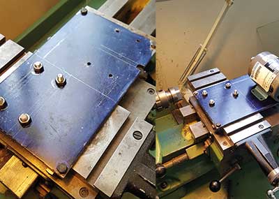
Figure 8. Secondary motor mounting setup.
With all the components made, I made my first attempt at assembly. It took four hours to setup, partly because I needed to find a way of attaching the blank to the mandrel, but predominantly because I was quite nervous so I took my time to check and re-check everything. After all, it had taken me a month to get this far!
To centre the Thornton cutter, I used a piece of blue pivot steel and then a reamer in the tailstock; the pivot steel was small enough to locate the centre and the reamer was to double check, due to it being machined concentric. The gib strips were then tightened to eliminate any movement which might occur from vibrations. And then, finally, I was ready! Figure 9.
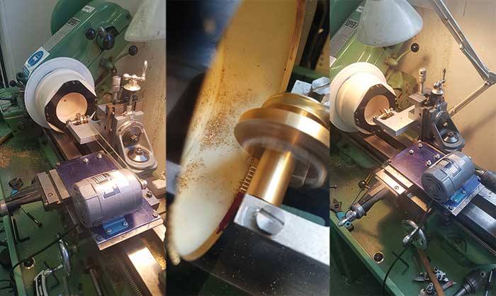
Figure 9. The internal teeth cutting setup.
First Attempt
The first attempt didn’t work at all!
Initially, everything seemed to be working perfectly and I had cut several teeth before I realised that something in the setup wasn’t right. It was also at this point, that the 20 other horology students who were watching me, decided I really was a crazy fool for taking on a clock like this!
The cutter made a good noise, so I couldn’t understand why it wasn’t working. But as can be seen in Figure 10, the resulting teeth were uneven and not properly formed.
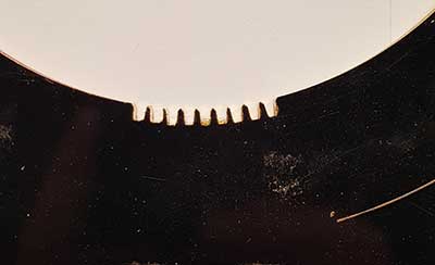
Figure 10. The uneven teeth.
After looking over the setup to see what could be wrong, I determined that the indexing setup had too much play because the silver steel was bowing in the middle of the mounting points. My course tutor suggested that I try a sturdier setup with three points of contact and a pin rather than a sprung piece of steel. So, a new setup was fabricated from pieces of steel box section and was welded up so it could be clamped to the floor of the lathe.
Finally, the pin was turned from silver steel, with a left over pillar sawn in half for a handle – I wasn’t one to waste material (I am a Yorkshireman after all). It wasn’t the prettiest setup, but it was now much more secure, Figure 11.
Attempt 2 and 3
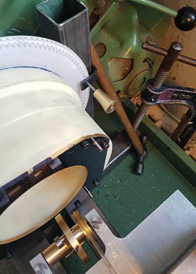
Figure 11. The new indexing setup.
I used the same blank for the second test and I couldn’t believe it: this time it worked perfectly, Figure 12. The teeth were equidistant, and the profile was correct. Phew! I can’t describe the relief I felt, as it was beginning to look like all my hard work might actually pay off!
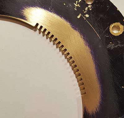
Figure 12. Second attempt at cutting internal teeth.
With this success, I was spurred on to setup another blank and attempt to cut the full wheel.
The third attempt was going well until I got halfway, and disaster struck AGAIN! A ball bearing on the rotor exploded, and that was the end of that. The setup was once again dissected to ascertain what had caused this, and I decided too much axial load had gone through the bearing.
This was the last attempt made before lockdown and the University shutting. I was gutted to be told that I wouldn’t be able to finish my clock, and all this coming just after I’d spent an entire month trying to create the annulus wheel.
However, I haven’t given up just yet. I am returning to Birmingham for a few days so that I can have another attempt at making the annulus wheel and spider arm. I’ve bought new bearings for the rotor which need pressing in, and then the setup is ready once again. The new bearings are specifically designed to take both radial and axial load.
In the next part of the article, I will detail the final steps of manufacturing the wheel and arm. I also want to look at the motion work of the clock which is really quite unique and explain how it works.
References
Gazely, W. J. (1956) Clock and Watch Escapements
Roberts, D. (1987), British Skeleton Clocks
Smith, W. R. (2003), How To Make A Strutt Epicyclic Train Clock
Unknown. (1831), ‘Memoirs of William Strutt’, Derby Mercury, 12 January, P3.