
In this month’s TimePiece, Frank Boswell describes how to refurbish an automatic device complete for a Rolex cal 1030. Any part reference numbers are taken from the Ebauches SA Technological Dictionary.
He writes…
On inspection there are three parts that require replacement. I thought the first challenge was making the oscillating weight retaining spring and for sure it did not disappoint. See Figure 1 for assembly with part fitted.
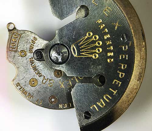
Fiigure 1.
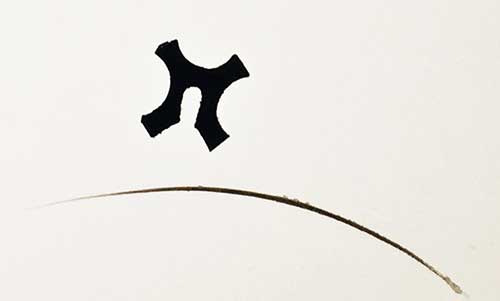
Figure 2 shows the part in isolation. Please note the eyelash in the picture which is 0.056mm thick to help relate to the actual size. I used a good quality spring steel 0.1mm thick, as I could not imagine trying to harden and temper something of this size singly.
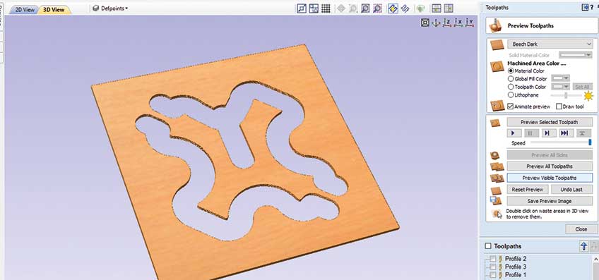
De-burring and polishing was difficult so I used the tab method as explained in previous issues see Figure 3. I can de-burr and polish both sides still attached to the parent metal. When I cut through the tabs, I used a pin vice to allow the dressing up of the tab. This is not a critical dimension but it finishes the appearance of the part. You can see the part fitted by referring back to Figure 1.
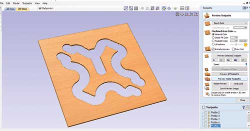
Figure 3.
I had to prove it’s operation as I did not have a sample, so I downloaded the image from www.watchparts.org
Fitting this in normal situations is difficult, so to help look at Figure 4.
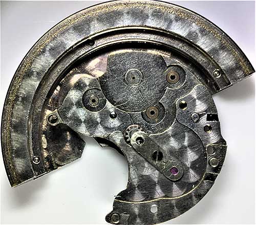
Figure 4.
From my bits box I found a suitable plate and utilised an existing screw hole to allow it to hold down the weight axle and drive gear. This saves a lot of searching time for the dreaded flirted spring.
The next stage was to tackle the driving and transmission wheels, see Figure 5, again with that eyelash. There is one tooth missing on both wheels also some distortion of others. I have taken off both pinion gears as the intention is to re-use them. To help with this, in both cases, I made the fit holes a little smaller, to allow an amount to be dressed off the pinion gear fit and to remove any previous peaning.
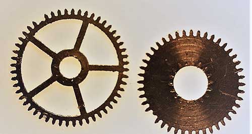
Figure 5.
Figure 6 shows both wheels as they have been extracted from the parent material. Figure 7 shows the tab method as explained which makes de-burring easy.
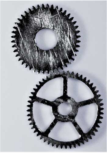
Figure 6.
Figure 7.After extraction I allowed 0.03mm for polishing to size. In the past I have been asked what module are the teeth. My answer: I don’t know. I try to reproduce what’s there. As I used a 0.2mm end mill, in both cases it is possible to machine from start to finish on one setting. The accuracy is only determined by the limits of the machine, which cost me £550.
My only regret is that these wheels are fitted to a watch that is sadly not mine. I would have used a tougher brass like aluminium bronze or one with a higher zinc content. I believe these were designed with safety in mind as an impact wheel, but replacements are not readily available. On more modern automatic calibres, the winding wheels are mainly steel.
I find with my machine, if the material is a little tougher on small parts it improves the definition, but I do accept that the machine with a few modifications is on the edge of its capabilities. Do not lose sight of the fact that anything larger than the above would be a walk in the park. Figure 8 shows the assembled unit ready for shipping to the customer.
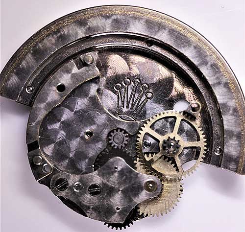
Figure 8.
A library of parts you can make is available in the CNC Section of the Guild’s Spare Parts Database on the website home page.