
A functional hand-made military style chronograph – Part 1
Introduction
Making watches has long been my main interest in horology and although the repair and restoration of watches has been the backbone of my workshop over three decades, it is the creation of timepieces which has captured my interest and devotion.
My interest lies not only in the creativity of the maker which I find expressed in a hand built watch, but also in understanding the sometimes complex processes involved. I am happy to embrace modern technology where it applies to horology as it can make the life of a watchmaker much easier and I have read with interest the recent TimePiece articles on CNC machining. When I made this VFR-Timer chronograph I tried to combine both traditional and modern workflows to make the required components. I have always been attracted to simplicity in watch design combined with elegance, but for me, above all, reigns the usability of the watch and the unambiguous transmission of information created and displayed by the watch.
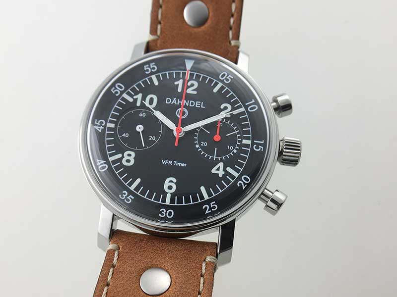
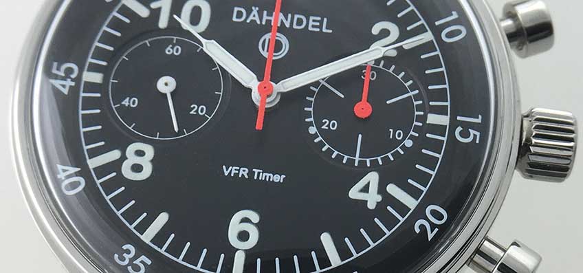
Figure 1. The VFR-Timer Chronograph.
Piloting small aircraft and understanding the restrictive environment in a small cockpit raised the desire to make a watch which I would find easy to use whilst flying.
There are many aviation-type watches on the market often displaying a multitude of functions, some of which simply do simply not apply when flying a small aircraft under VFR (Visual Flight Rule) conditions. Therefore, I wanted a simple chronograph which still enabled me to read the time indications when, for example, my arm was stretched out operating some of the cockpit controls. At the same time I was aiming to create a watch which not only acts as an instrument, but has a degree of elegance so it doesn’t look out of place for daily wear.
Design and Preparation
I started the design with a rough pencil sketch of the watch on a piece of scrappaper and then proceeded to drawing the dial layout with TurboCad in 2D mode. The inspiration came from a 1940s fighter aircraft cockpit clock which has a classic, easy to read military style dial, showing just time, stop-time, and nothing else.
Figure 2. Classic aircraft cockpit style.
As always when I design a watch dial, I print out mock dials on strong quality paper to check the design scaled down to its actual size. This method is a great help to simulate the finished dial and to try it with different hands and view angles, etc.
For the movement I choose the iconic Valjoux 7733 chronograph calibre, known for its ruggedness and reliability. This calibre and its variants was used by a number of watch manufacturers in the late 1960s and early 70s and can be found in vintage Breitling, Tag-Heuer, Tudor and other chronographs. It has a classic bi-compax layout and is cam operated rather than fitted with a column wheel. For the type of watch I was going to build it represented the perfect choice not least because of its vintage heritage.
The case material I selected is 316L stainless steel because of it’s durability and the possibility of being able to re-finish the case by simple means in years to come. After long consideration it was decided to make the first three chronographs of the series with a classic domed acrylic glass rather than a Sapphire glass in order to introduce a kind of classic and vintage aesthetic which cannot easily be achieved with a modern glass. It also has the advantage that I could realise a design with a front fitted movement and dial in combination with a relatively low and thin glass rim. I had recently noted this configuration had been successfully used by a couple of watch manufacturers on their retro style watches. The case back on the VFR-Timer is, however, fitted with a flat Sapphire crystal to allow a view of the movement.
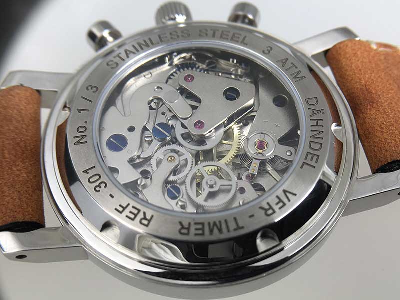
Figure 3. View of the finished movement through the Sapphire glass.
When designing a watch using classic chronograph calibres such as the 7733 the movement thickness can become a challenge especially when the proposed watch is supposed to have a flat dial and reasonably balanced proportions.
I have never been a friend of chunky watches and some of the 60s and 70s case styles for chronographs can be a little monolithic to say the least. By using the above described classic configuration I could bring down the perceived case height to a minimum.
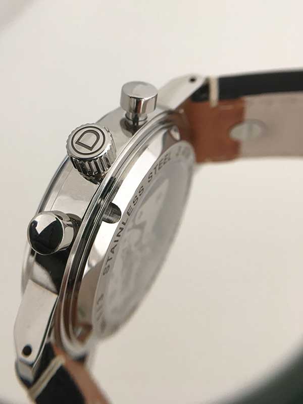
Figure 4. Vintage case style and proportions.
Before I started work a lot of time was spent in preparing the workshop for producing the required components. Manydifferent work holding adapters had to be made to be able to machine the case and dial. Various purpose made carbide end mills of different diameters and shapes were purchased to deal with milling 316 stainless steel accurately and efficiently. Drills, thread cutters and specially modified lathe cutting tools all had to be ready before work started. All these preparations of course are aimed at producing a small series of components, rather than a one-off part, and quality cutting tools will speed up the processes considerably. The same can be said for abrasives and polishing materials.
Dial and hands
The manufacture of printed dials is a very specialised task and there are not an abundance of firms to choose from. The majority of existing manufacturers who are able to produce dials to an industrial quality standard tend to work with large numbers, a minimum of one hundred or more units. For small series and, of course, for prototype prints this is not suitable and the cost would be prohibitive. After a lot of research I located a firm who was able to print 20 to 30 units at a time, but with consistent quality.
For the first three chronographs I produced the dial blanks in my own workshop where the discs were cut from brass sheet and then machined on the lathe to create recesses for the flanged dial feet on the rear and lowered sub dials on the front.
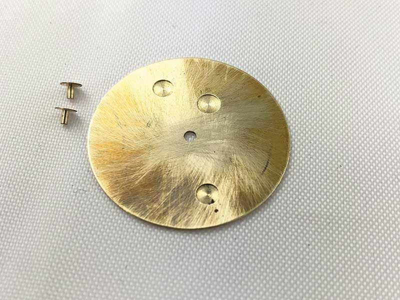
Figure 5. Dial blank and dial feet before soldering.
Flanged dial feet cut from hard brass were then set into the recesses on the back of the dial with strong silver solder. These dial blanks tend to warp due to machining and soldering and it is important that they are individually checked and flattened again before they are printed.
Colouring and print was applied by the dial printers, with part of the indicators printed in Superluminova C1 to give partial night readability to the dial. The blanks for the hands were supplied to measure by a small specialised workshop before being finished, painted, and filled with Superluminova in my own premises.
Case and crown
The case and caseback are milled from solid 316L S/S bar which was obtained in 1.50 metre lengths in various diameters. The blanks for machining are produced by cutting off discs of the required thickness with an electric bench saw.
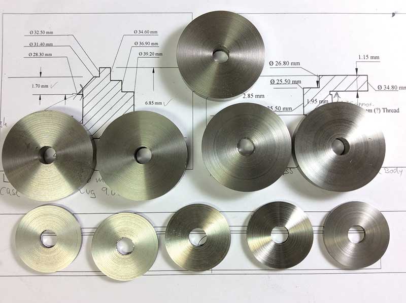
Figure 6. 316L stainless steel blanks ready for machining.
It is perhaps important to stress that the grade of stainless steel used has to be correct and not all variants of the 316 family of S/S are suitable for machining into watch cases because of the fine and intricate cuts required. In the past I have made watchcases and case parts from plain 316 steel which requires a lot more work and does not polish up as well as 316L.
The blanks are fitted up in the lathe and all interior diameters including the glass seat and case back thread are machined, before they are fitted to a specially made adapter spindle to cut all outside surfaces and angles
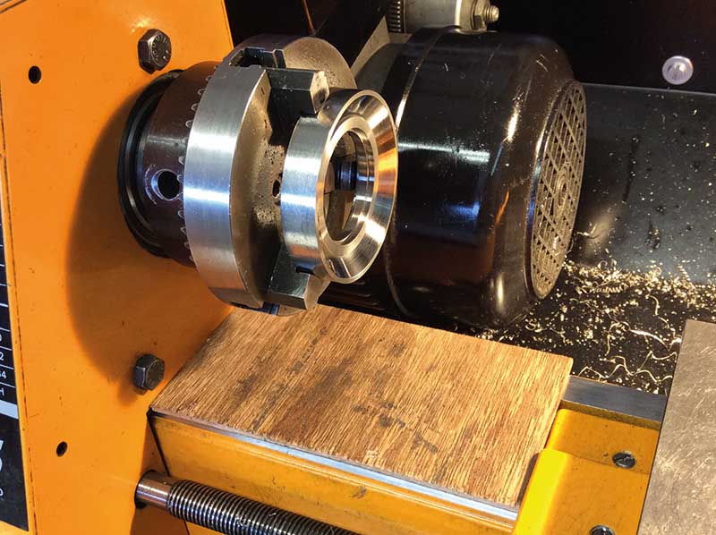
Figure 7. Back of watch case main body before threading.
It is advisable to remove burrs from the S/S whilst chucked in the lathe as it can take quite a lot of extra work to deal with them afterwards.
Whilst machining the cases I worked from sketches and notes rather than CAD drawings. Although I have made some drawings afterwards I prefer to work this way, especially if I still want to gradually perfect the shape and appearance of a part. I never spend too much time with computerised simulations of dials and
indeed case parts, because I find that no matter how impressive they appear to be on my 27 inch screen, the best way to get a feel for and control the proportions of case parts is to see them evolve slowly during machining. The time spent making a work holding spindle for various case cuts is time especially well spent, as the spindle enables me to remove and refit the work quickly and accurately. This way I can check and adjust shapes, angles and proportions as I go along, as you can see in Figures 8, 9, 10.
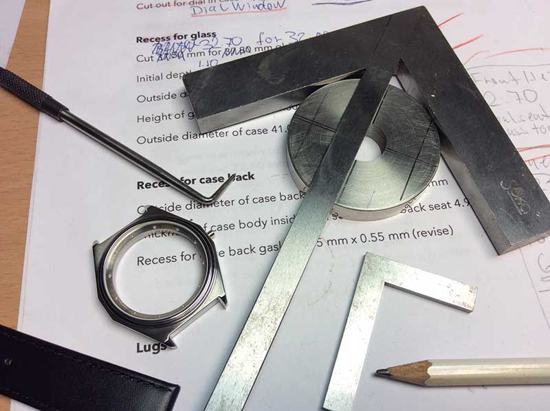
Figure 8. Method of developing prototype watch cases.
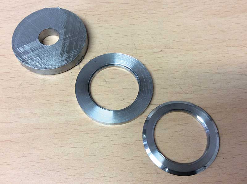
Figure 9. Three different stages of machining a watch case part.
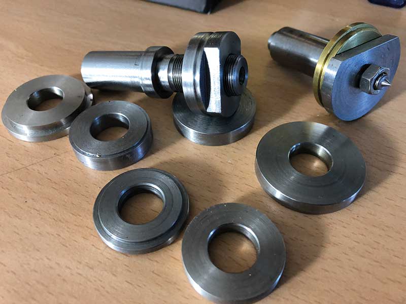
Figure 10. Work holding spindles and adapters.
After machining the case parts on the lathe is finished the work is transferred to the milling machine for further machining. The work holding spindle is used again to hold the work securely in the mill. Milling operations start with milling the space
between the lugs using a straight end mill and a dove-tail cutter. Next is finishing all exterior cuts and drilling the holes for the spring bars. Once the bulk of material has been removed, the holes for the crown tube and pushers are drilled and the pusher threads are cut. Some small recesses on the inside of the case body and the slots for the case opening key are cut on a smaller machine, which leaves the setup of the larger mill unaltered for further cases to be machined, Figure 11, 12, 13.
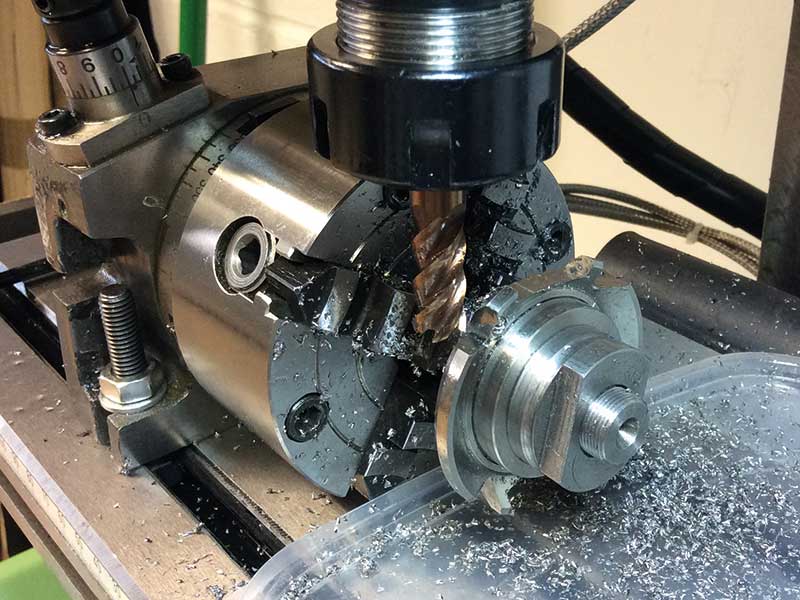
Figure 11. Milling the outside of the watch case.
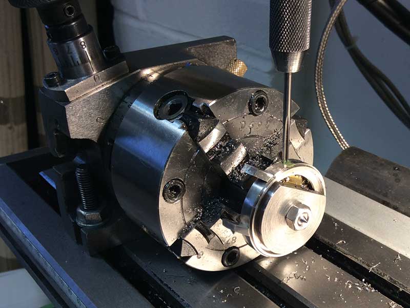
Figure 12. Tapping the pusher holes in the case.
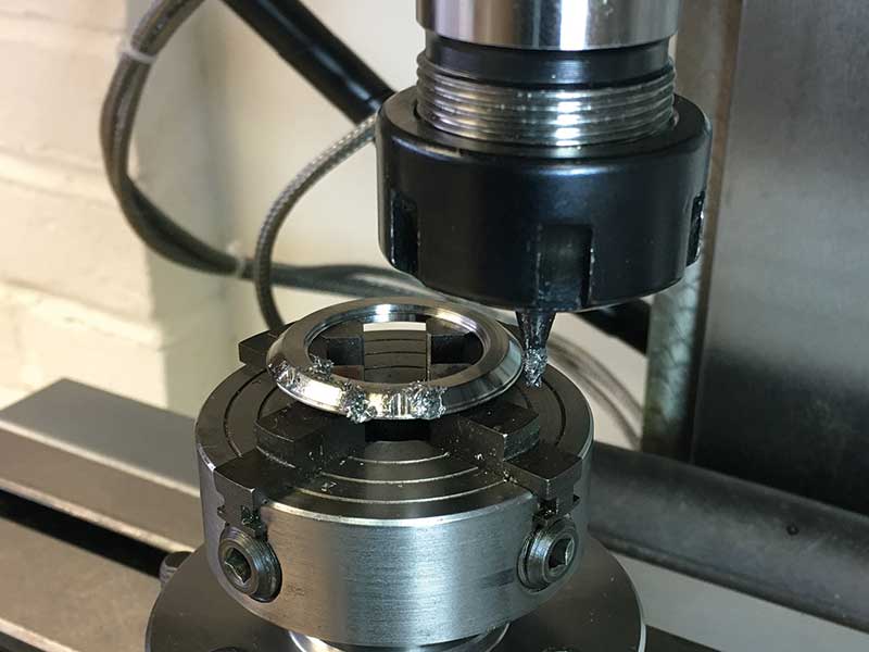
Figure 13. Milling the case opening slots.
After the first case for a new watch is finished in the way described it would of course be easy to submit the case and appropriate drawings to a manufacturer for watch cases and have them produced in larger numbers on high tech CNC
machines, but this is not the kind of watch I wanted to make in this instance. The method I use enables me to vary my design quickly if desired and use vintage NOS movement calibres which are not usually available in large numbers anyway. Heights for stem and pusher holes usually vary as well as movement diameters, recesses and so on.
Before the cases receive their finish, they are tested for accuracy by fitting a movement with dial and stem, as well as a glass. Machining marks are then removed by hand from case body and case back before they undergo different stages of polishing.
One part which I did design entirely on the computer was the crown with logo. Making crowns in my workshop in the quality and quantity I wanted was not an option as I do not possess the machinery required to make 30 crowns or more to a standard I would be happy with. Luckily I found a crown manufacturer who could do these for me according to my drawings, again in 316L in a beautiful finish. (See Figure 3).
In Part 2 you can read about the movement and find out how the watch was assembled and finished.
Günter will also reveal more about exciting future projects that he is already working on.